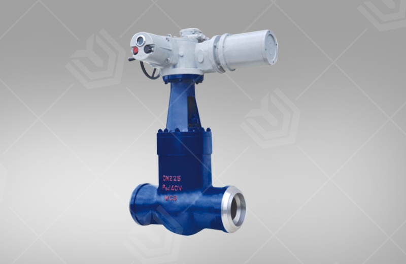


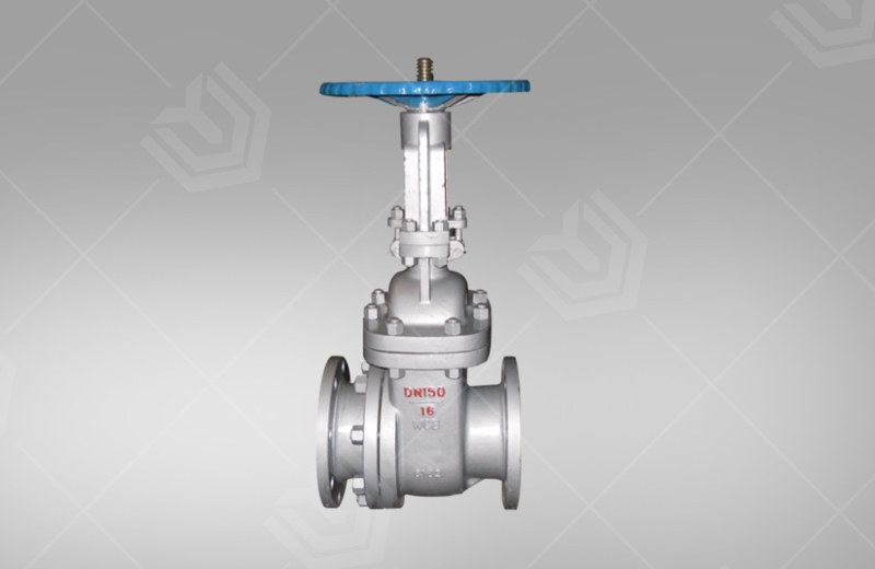
Slag gate valve
Technical Parameter
Item model number: PZ41HNominal diameter: DN50~500mmNominal pressure: PN1.6~6.4MPaWorking temperature: 0~100℃Applicable medium: grey water mixtureMain material: WCB, WCB+ wear-resistant alloyDesign and manufacture: GB/T12234, GB/T2595Flange standard: GB/T9113, JB/T79
Product Detail
Product Description
Features
1. The middle flange bolt connection is adopted, and the two ends of the branch pipe are flange connection or butt welding connection.2. The opening and closing parts are forcedly sealed by semi-sealing pair, with excellent performance.3. The material of the sealing pair is wear-resistant ceramic or wear-resistant alloy, which has strong wear resistance, strong wear resistance, durable erosion, scratch resistance, low friction, and reliable sealing.4. The outlet flow passage of the valve body has a reasonable structure, no slag, flexible opening and closing, and no jamming.5. The valve stem is quenched and tempered and surface nitrided, which has good corrosion resistance, scratch resistance and wear resistance.6. The medium and large diameters are equipped with rolling bearings, which can be easily opened and closed.Main performance specifications
| Model | Nominal pressure | Test pressure | Proper temperature | Applicable media | |
| Strength test | Seal test | ||||
| 1.6 | 2.4 | 1.8 | 22.0 | ≤100℃ | Grey water mixture, slag water ratio 1:6Maximum particle size<50mm |
| 2.5 | 3.8 | 2.8 | 27.5 | ||
| 4.0 | 6.0 | 4.4 | 35.2 | ||
| 6.4 | 9.6 | 7.1 | 22.0 | ||
Material of main parts
| Body | WCB | |
| Bonnet | WCB | |
| Bracket | WCB | |
| Gate | WCB+Wear-resistant alloy | WCB+ceramics |
| Stem | 2Cr13 | |
| Seat | WCB+Wear-resistant alloy | WCB+ceramics |
| Seal ring | Reinforced flexible graphite | |
| Packing | Reinforced flexible graphite | |
| Stem Nut | ZCuA110Fe3 | |
")
Main external connection dimensions(PN16/25)
| DN | L | D | D1 | D2 | b | z×d | f | H | H1 |
| 50 | 250 | 165 | 102 | 99 | 20 | 4×18 | 3 | 420 | 335 |
| 80 | 280 | 200 | 133 | 132 | 22 | 8×18 | 3 | 615 | 510 |
| 100 | 300 | 220 | 180 | 158 | 24 | 8×18 | 3 | 805 | 685 |
| 150 | 350 | 285 | 240 | 212 | 28 | 8×22 | 3 | 952 | 790 |
| 200 | 400 | 340 | 295 | 268 | 30 | 12×22 | 3 | 1085 | 885 |
| 250 | 450 | 405 | 355 | 320 | 32 | 12×26 | 3 | 1235 | 1015 |
| 300 | 500 | 460 | 410 | 370 | 34 | 12×26 | 4 | 1450 | 1190 |
| 350 | 550 | 520 | 470 | 430 | 38 | 16×26 | 4 | 1640 | 1350 |
| 400 | 600 | 580 | 525 | 482 | 40 | 16×30 | 4 | 1798 | 1460 |
| 450 | 650 | 640 | 585 | 532 | 44 | 21×30 | 4 | 1980 | 1620 |
| 500 | 700 | 715 | 650 | 585 | 46 | 20×33 | 4 | 2190 | 1800 |
Main external connection dimensions(PN40)
| DN | L | D | D1 | D2 | b | z×d | f | H | H1 |
| 50 | 250 | 165 | 125 | 88 | 20 | 4×18 | 3 | 444 | 340 |
| 80 | 310 | 200 | 160 | 121 | 22 | 8×18 | 3 | 636 | 508 |
| 100 | 350 | 235 | 190 | 150 | 24 | 8×22 | 3.5 | 930 | 680 |
| 150 | 450 | 300 | 250 | 204 | 30 | 8×26 | 3.5 | 984 | 800 |
| 200 | 550 | 375 | 320 | 260 | 38 | 12×30 | 3.5 | 1094 | 875 |
| 250 | 650 | 450 | 382 | 313 | 42 | 12×33 | 3.5 | 1270 | 1010 |
| 300 | 750 | 515 | 450 | 364 | 46 | 16×33 | 3.5 | 1470 | 1180 |
| 350 | 850 | 580 | 510 | 422 | 52 | 16×36 | 4 | 1555 | 1245 |
| 400 | 950 | 660 | 585 | 474 | 58 | 16×39 | 4 | 1650 | 1280 |
| 450 | 4050 | 685 | 610 | 524 | 60 | 20×39 | 4 | 1817 | 1415 |
| 500 | 1150 | 755 | 670 | 576 | 62 | 20×42 | 4 | 1990 | 1560 |
Main external connection dimensions(PN64)
| N | L | D | D1 | D2 | b | z×d | f | H | H1 |
| 50 | 250 | 180 | 135 | 88 | 26 | 4×22 | 3 | 444 | 340 |
| 80 | 310 | 215 | 170 | 121 | 30 | 8×22 | 3 | 636 | 508 |
| 100 | 350 | 250 | 200 | 150 | 32 | 8×26 | 3.5 | 830 | 680 |
| 150 | 450 | 345 | 280 | 204 | 38 | 8×33 | 3.5 | 984 | 800 |
| 200 | 550 | 415 | 345 | 260 | 44 | 12×36 | 3.5 | 1094 | 875 |
| 250 | 650 | 470 | 400 | 212 | 48 | 12×36 | 3.5 | 1270 | 1010 |
| 300 | 750 | 530 | 460 | 364 | 54 | 16×36 | 3.5 | 1470 | 1180 |
| 350 | 850 | 600 | 525 | 422 | 60 | 16×39 | 4 | 1555 | - |
| 400 | 950 | 670 | 585 | 474 | 66 | 16×42 | 4 | 1650 | 1280 |
| 450 | 1050 | 715 | 630 | 524 | 70 | 20×42 | 4 | 1817 | 1415 |
| 500 | 1150 | 800 | 705 | 476 | 76 | 20×48 | 4 | 1990 | 1560 |